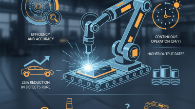
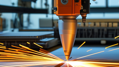
Robotic welding uses programmed machines to join metal parts with an electric arc, laser, or resistance process. A typical system includes a robot arm, welding torch, power source, controller, positioner, and safety enclosure. Together, these components guide heat and filler material along a planned joint. Robotic welding is not simply automatic welding. It is a coordinated process that depends on accurate programming, stable fixtures, suitable materials, and consistent part placement.
The operator usually loads parts into a fixture, checks joint alignment, and teaches the robot its movement path. The controller then manages travel speed, torch angle, wire feed, and welding current. Sensors may detect joint position or correct small variations. The arc is precise. However, the result still depends on practical details. A loose clamp can create porosity, uneven penetration, or excessive spatter. A robot can repeat a bad setup perfectly. That weakness matters.
In production environments, technicians inspect test beads, adjust parameters, and monitor equipment before full operation. Qualified welding professionals also verify procedures against relevant industry requirements and manufacturer guidance. Robotic welding can improve repeatability, reduce operator exposure to heat, and support higher production rates. It does not remove the need for human judgment. Someone must select the process, evaluate weld quality, maintain the system, and respond when conditions change. Even advanced systems have limits. Dirty surfaces, distorted parts, or poor programming can reduce performance quickly. Understanding how the robot, welding process, and surrounding equipment work together gives manufacturers a more reliable foundation for safe and consistent results.
What Is Robotic Welding and How Does It Work?
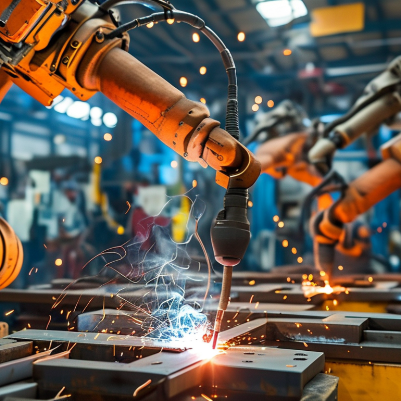
Robotic welding uses a programmed mechanical arm to move a welding torch along a planned path. A controller coordinates torch movement, welding current, travel speed, and shielding gas. Fixtures hold parts in consistent positions while sensors may detect seams or changes in joint location.
The main difference from manual welding is control and adaptability. A skilled welder watches the arc, adjusts hand position, and responds to gaps or distortion immediately. A robot repeats programmed movements with impressive consistency, especially during long production runs. However, it does not automatically produce better welds. Poor fixture design, incorrect settings, or contaminated metal can create repeated defects. That assumption needs challenging. Manual welding remains valuable for prototypes, repairs, complex joints, and short production runs. Robotic welding usually needs careful programming, maintenance, and inspection.
Tips: Clean the joint before welding. Check fixture alignment often. Test the program on sample parts. Use qualified personnel to verify penetration, bead shape, and heat input. Keep records of adjustments. Small changes matter. A slightly incorrect torch angle can weaken the joint or increase spatter. Operators should also review robot performance instead of trusting every cycle blindly. Even reliable systems need human judgment.
Robotic welding uses programmable industrial robots to position the welding torch and repeat a defined sequence. Compared with manual welding, it generally provides a higher arc-on time, more consistent motion, and less direct operator exposure to the welding arc.
The chart shows commonly reported industrial ranges for arc-on time, meaning the percentage of production time during which the welding arc is actively operating. Actual results vary with part geometry, fixtures, material, joint design, and production requirements.
What Is Robotic Welding and How Does It Work?
The Main Components of a Robotic Welding System
A robotic welding system combines motion control, electrical power, sensing, and carefully prepared fixtures. Its central unit is the industrial robot arm. It moves the welding torch along programmed paths, often within fractions of a millimeter. A controller coordinates speed, position, and welding sequences. The power source creates the arc, while the wire feeder supplies consistent filler metal. Small changes matter.
The torch assembly includes a contact tip, shielding-gas nozzle, and cable package. Gas protects the molten weld pool from atmospheric contamination. A positioner rotates the workpiece, helping the torch maintain a stable angle. Fixtures hold parts firmly and repeatably. Without them, even an accurate robot may produce inconsistent joints. That is an uncomfortable truth.
Sensors can detect seam location, wire touch-off, or torch distance. Vision systems may inspect fit-up before welding, although they cannot correct every poor joint. Operators still teach paths, verify parameters, clean nozzles, and inspect finished welds. The safety cell adds guarding, interlocks, emergency stops, and controlled access.
The International Federation of Robotics reported 541,302 industrial robots installed worldwide in 2023. Its World Robotics 2024 report also recorded more than 4.2 million robots operating globally. These figures show the scale of industrial automation, not guaranteed welding quality. Poor fixture design remains a practical failure point. A robotic system is only as reliable as its process preparation, maintenance, and human oversight.
What Is Robotic Welding and How Does It Work?
How a Robot Prepares and Positions Metal Parts
Robotic welding begins before the arc starts. Workers load steel, aluminum, or other approved metals into a fixture. The fixture holds each part against defined stops. Clean contact surfaces matter. Oil, scale, and loose debris can shift the joint or weaken the weld.
A robot may use cameras, touch sensing, or laser tracking to locate each part. Its controller compares measured points with the programmed model. If the position is acceptable, clamps secure the assembly. The robot then checks its tool center point, travel angle, and working distance. Small changes matter. A gap of only a few millimeters can alter heat distribution and penetration.
Industrial adoption is expanding. The International Federation of Robotics reported 541,302 new industrial robots installed worldwide in 2023, according to World Robotics 2024. Its operational stock exceeded 4.2 million units. Welding cells contribute to this growth because they repeat difficult movements with steady timing. Still, preparation is not automatic perfection. Fixtures wear, parts vary, and sensors can misread reflective surfaces. This is where shop-floor experience remains essential. Technicians often adjust clamps, refine approach points, and inspect the first weld manually. A neat simulation can still meet a messy production floor.
| Process Stage | Robot or System Action | Key Data Dimension | Typical Information | Purpose in the Welding Process |
|---|---|---|---|---|
| 1. Part Loading | The operator or an automated material-handling system places metal parts into a fixture. | Part condition | Clean, correctly oriented, and free from excessive oil, scale, or loose contamination. | Creates a consistent starting position before the robot begins its programmed cycle. |
| 2. Fixturing | Clamps, locators, and supports hold the components in the required relationship. | Joint alignment | Controls gap, overlap, angle, and movement caused by welding heat. | Reduces distortion and helps maintain repeatable weld-joint geometry. |
| 3. Part Identification | A sensor, barcode system, or production-control signal confirms the correct part and welding program. | Program selection | Recipe may include travel path, welding current, voltage, wire-feed speed, and shielding-gas settings. | Prevents the robot from applying the wrong sequence or parameters to a part. |
| 4. Position Verification | Touch sensing, vision, or other sensors check the actual location of the joint relative to the programmed path. | Location correction | Detects part tolerances, fixture variation, and small changes in joint position. | Allows the system to adjust the path so the welding tool follows the joint more accurately. |
| 5. Tool Approach | The robot moves the welding torch to the programmed approach point while maintaining a safe clearance. | Torch orientation | Maintains the required work angle, travel angle, and distance from the workpiece. | Supports stable arc initiation and helps prevent collisions with the fixture or part. |
| 6. Welding Setup | The controller activates the welding power source, shielding gas, wire feeder, and related equipment. | Process parameters | Common variables include current, voltage, wire-feed speed, travel speed, gas flow, and polarity. | Matches the welding conditions to the material, joint design, and required weld size. |
| 7. Weld Path Execution | The robot moves the torch along a programmed path at a controlled speed and orientation. | Motion control | Path may include straight travel, weaving, pauses, starts, stops, and changes in torch angle. | Produces consistent weld placement and repeatable movement from part to part. |
| 8. Heat Management | The system controls travel speed, weld sequence, and intermittent weld timing to manage heat input. | Thermal control | Heat input is influenced by welding current, voltage, travel speed, and arc-on time. | Helps limit distortion, burn-through, excessive penetration, and undesirable metallurgical effects. |
| 9. Positioner Coordination | A coordinated positioner may rotate or tilt the workpiece while the robot welds. | Work angle | Places the joint in a more favorable welding position and can reduce difficult overhead operations. | Improves access, weld-pool control, and continuity along complex joints. |
| 10. Weld Completion | The robot completes the programmed weld, extinguishes the arc, and returns the torch to a safe position. | Cycle sequence | May include crater fill, burn-back control, post-flow shielding, and torch retraction. | Helps reduce defects at the start and end of the weld and prepares the cell for the next cycle. |
| 11. Inspection | An operator or inspection system checks weld appearance, dimensions, continuity, and visible defects. | Quality criteria | Typical checks include weld size, profile, undercut, porosity indications, cracks, spatter, and joint coverage. | Confirms whether the finished weld meets the applicable drawing, procedure, and quality requirements. |
| 12. Data Recording | The control system may store cycle status, alarms, parameter values, and inspection results. | Traceability | Records can link a part to its welding program, process conditions, operator actions, and inspection outcome. | Supports troubleshooting, preventive maintenance, process improvement, and production documentation. |
Robotic welding is a controlled sequence of movements, heat, and material flow. The process begins with a digital weld plan. Engineers define joint locations, torch angles, travel speeds, wire feed rates, voltage, and shielding gas. They then enter these values through a teach pendant or offline programming software. The robot moves through each point while the welding power source follows the selected procedure.
A technician usually teaches the torch position by guiding it around the workpiece. Small details matter. The torch must approach the joint consistently. Sensors may detect seam location and correct minor shifts in part placement. The controller then repeats the path, while operators monitor arc stability, spatter, and bead shape. According to the International Federation of Robotics’ World Robotics 2024 report, factories installed 541,302 industrial robots in 2023. That scale shows why repeatable programming has become important.
Testing remains essential. A perfect simulation cannot predict every gap, reflection, or contaminated surface. Operators inspect sample welds and adjust speed, current, or torch distance. Sometimes, the first program is wrong. That is normal, but it should not be ignored. The American Welding Society projects that the United States may need 330,000 new welding professionals by 2028, making automated cells valuable for production support, not human judgment replacement. The strongest process combines programmed consistency with experienced review.
What Is Robotic Welding and How Does It Work?
Robotic welding uses programmed machines to guide a welding torch along precise joint paths. Sensors, fixtures, and control software coordinate movement, heat, wire speed, and shielding gas. Operators prepare the workpiece, load the program, and monitor the welding cell. This process creates repeatable welds, even during long production runs. However, automation is not magic. A poorly aligned joint can still produce a weak weld.
Quality depends on stable settings and regular inspection. Cameras or sensors can detect gaps, position changes, and surface defects before they become costly problems. Test welds, visual checks, and non-destructive testing provide stronger evidence than appearance alone. Safety improves because workers spend less time near arc radiation, fumes, sparks, and hot metal. Physical separation is still essential. Guards, interlocks, ventilation, and emergency controls must work correctly every day. Efficiency increases through steady cycle times and reduced manual repositioning, though setup can require careful planning and skilled judgment.
Tips: Clean the joint before welding. Check fixture alignment every shift. Record parameter changes. Train operators to recognize unusual sounds, spatter, or torch drift. Review failures honestly; small defects often reveal larger process problems. A robot repeats instructions faithfully, including mistakes.