


What Is a Turning Tool Holder?
A Turning Tool Holder is the component that secures a cutting tool in a lathe or turning center. It positions the tool against the workpiece and helps maintain a stable cutting edge as material is removed. The holder may look simple, but its geometry, clamping method, and fit can affect accuracy, surface finish, and tool life. Small part. Big effect.
Common designs include external turning holders, boring-bar holders, and holders for grooving or threading. Each supports a different operation and cutting direction. For example, an external holder may carry an indexable insert across a rotating shaft, while a boring bar reaches into a hole. The right choice depends on the machine, insert shape, workpiece material, and available clearance. A holder that fits one setup may cause chatter or poor access in another.
This guide explains how a Turning Tool Holder works, how major holder styles differ, and what to check before selecting one. It also covers practical details such as shank size, insert compatibility, rigidity, and cutting orientation. Always compare the holder’s specifications with the machine and tooling manufacturer’s guidance. A chart can narrow the options, but it cannot describe every real setup. That part takes judgment, and sometimes a test cut. Tool wear, chip control, and finish provide useful feedback. Understanding those signals makes holder selection more deliberate, though not perfectly predictable.
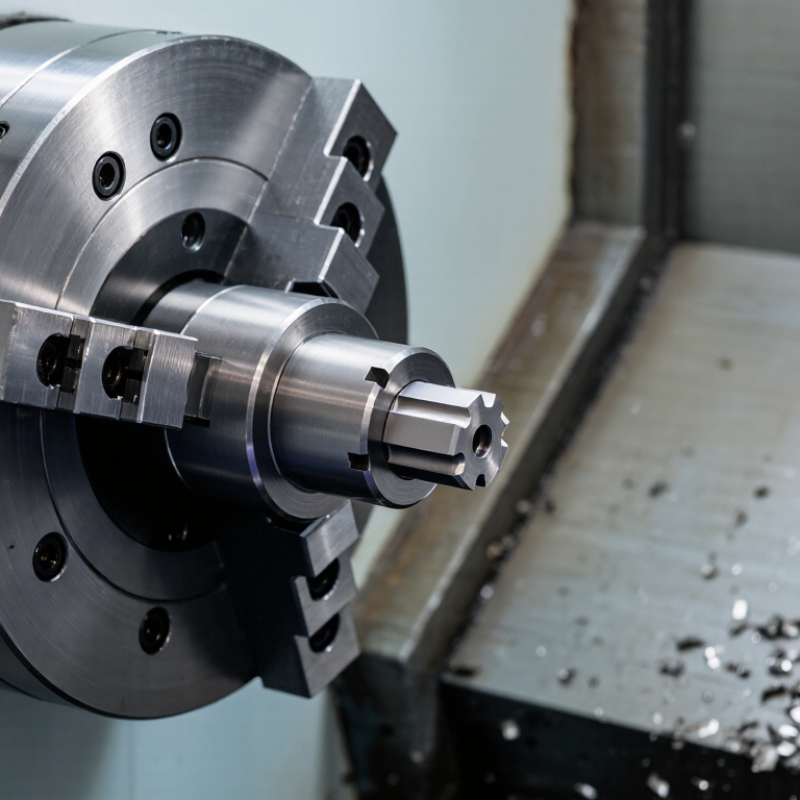
Definition and Purpose of a Turning Tool Holder
What Is a Turning Tool Holder?
Definition and Purpose of a Turning Tool Holder
A turning tool holder is the component that secures a cutting tool in a lathe. It keeps the cutting edge in position as the workpiece rotates. Its purpose is practical: hold the tool firmly, present it at the correct height, and help resist cutting forces. A typical holder has a pocket or clamp for an insert, plus a shank that fits the machine’s tool post or turret. Small part. Big effect. Even a slight shift can leave a rough surface or uneven dimensions.
The holder also affects how smoothly heat and vibration are managed during cutting. A rigid setup, with minimal tool overhang, usually helps reduce chatter. Overhang is easy to overlook. Yet a long, unsupported tool can flex under load, especially during heavier cuts. Choosing a holder means checking its size, insert compatibility, cutting direction, and clearance around the workpiece. The right fit depends on the lathe and the operation, not just the tool’s appearance. A holder cannot compensate for poor setup or a worn insert, either. It is worth checking alignment and clamping before machining; small setup errors can be stubborn to diagnose later.
What Is a Turning Tool Holder? — Definition and Purpose
| Holder Type | Definition and Purpose | Typical Turning Operation | Key Selection Considerations |
|---|---|---|---|
| External turning holder | Clamps a cutting insert and positions its cutting edge against the outside surface of a rotating workpiece. | Facing, straight turning, and shoulder turning. | Match the holder to the insert shape and size, required approach angle, cutting direction, workpiece material, and machine setup. |
| Boring bar | Holds an insert on a bar that extends into a pre-existing hole to machine its internal surface. | Internal turning and enlarging or finishing bores. | Choose a bar diameter that fits the bore and provides adequate clearance. Longer overhangs generally increase vibration risk; a larger, shorter bar is usually more rigid when the setup allows. |
| Threading holder | Positions a threading insert so it can form a screw thread as the workpiece rotates and the tool follows a controlled feed path. | External or internal thread cutting. | Confirm the insert profile and pitch range, thread form, internal or external use, and required tool orientation. |
| Grooving holder | Supports a narrow insert designed to cut a groove of a specified width and depth. | Groove cutting, undercutting, and some face-grooving operations. | Check insert width, groove depth, clearance, holder reach, and chip evacuation. Use a face-grooving setup only when the holder and insert are designed for it. |
| Parting holder | Holds a narrow blade or insert that cuts across the workpiece to separate a finished part from the remaining stock. | Parting-off on a lathe. | Tool alignment, blade projection, workpiece support, and coolant access can affect stability and cutting performance. |
| Right-hand, left-hand, or neutral holder | Describes the holder’s intended cutting direction or orientation; the correct choice depends on the lathe setup and direction of feed. | External turning, facing, or other operations where tool approach and feed direction matter. | Check the machine’s spindle rotation, turret position, tool approach, and planned feed direction rather than relying on the label alone. |
| Shank and clamping interface | The shank connects the holder to the tool post, turret, or other machine interface. It helps locate and secure the cutting tool. | All turning operations. | Verify shank dimensions, mounting compatibility, holder orientation, and secure clamping. The holder must fit the machine’s tool station. |
| Insert clamping system | The screw, lever, clamp, or other mechanism holds the insert in its pocket and helps maintain its position during cutting. | All insert-based turning operations. | Use an insert specified for the holder’s pocket and clamping method. Keep mating surfaces clean and follow the toolmaker’s recommended tightening procedure. |
In brief: A turning tool holder is the component that secures and positions a cutting tool or insert on a lathe. Holder and insert compatibility, machine fit, cutting direction, operation, and setup rigidity all matter; exact dimensions and designations vary by tooling system.