What Is CAD CAM Software for Plasma Cutting?

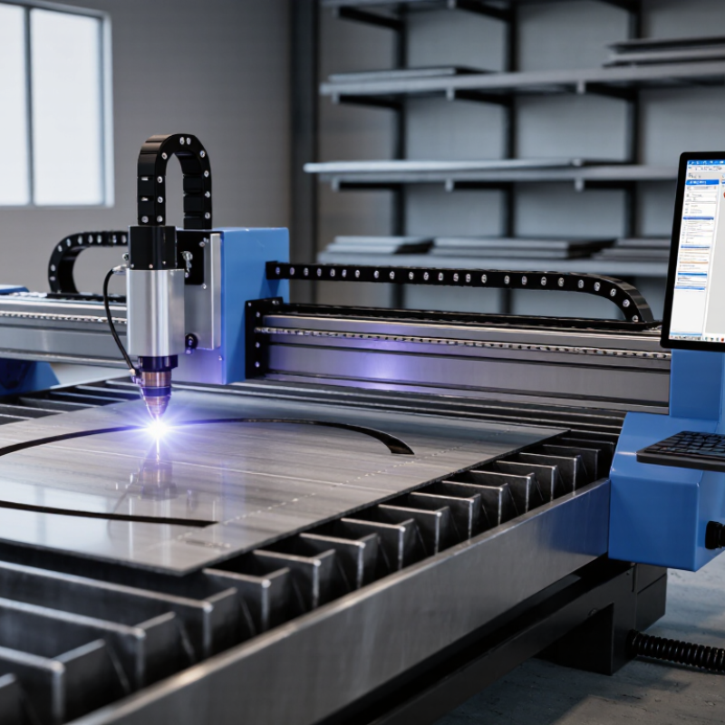
CAD CAM software for plasma cutting connects a digital drawing with a controlled, physical cut. It helps transform CAD files into toolpaths that a plasma table can understand. The software considers material thickness, torch height, cutting speed, kerf width, lead-ins, and pierce points. These details matter when a steel plate must become a clean bracket, sign, or machine component.

Jim Colt, a longtime plasma-cutting specialist and former Hypertherm training manager, has often emphasized a practical truth: “A good cut begins before the torch fires.” That idea captures the software’s real value. It is not merely a button for generating G-code. It helps operators prepare the job, reduce wasted metal, and identify design problems before production begins. A poorly placed lead-in can leave a visible mark. Incorrect pierce settings can create extra dross beneath the plate.

In this guide, we will examine what CAD CAM software for plasma cutting does, how its workflow operates, and which features deserve attention. We will also consider nesting, post-processors, machine compatibility, and cut-quality controls. Some software promises automation, but automation is never perfect. Operators still need practical judgment. A drawing can look accurate on screen and fail on the shop floor.

That gap deserves attention. Real performance depends on the machine, consumables, material, and operator experience. By understanding these limits, buyers can choose software more confidently and use it responsibly.
What Is CAD CAM Software for Plasma Cutting?

What CAD CAM Software Means in Plasma Cutting

What CAD CAM Software Means in Plasma Cutting

CAD CAM software links a digital drawing with the physical movement of a plasma torch. CAD defines the part’s shape, including holes, slots, and outside profiles. CAM converts that geometry into toolpaths, cutting speeds, pierce delays, and torch-height commands. It also compensates for kerf, the narrow material removed by the arc. A 6 mm plate may need a different kerf value than a 12 mm plate. Small settings create visible differences.

The software also nests parts across a sheet to reduce waste. Grand View Research estimated the global CAD software market at about $10.9 billion in 2023, with continued growth through 2030. That figure covers many industries, not plasma cutting alone, but it shows how central digital design has become. The 2024 World Robotics report recorded 541,302 industrial robot installations worldwide during 2023. Automated cutting benefits from the same data-driven production approach.

Real experience still matters. A clean simulation cannot detect every warped sheet, worn electrode, or unstable air supply. Operators must review lead-ins near corners and inspect the first cut. Sometimes the calculated path looks efficient but leaves excessive heat at small holes. That is where software needs judgment. ISO 9013 provides quality classifications for thermally cut surfaces, giving teams a consistent way to inspect bevel, roughness, and dimensional accuracy. CAD CAM is powerful, but it is not a substitute for measurement, maintenance, or honest correction.

How CAD Designs Become Plasma Cutting Toolpaths

What Is CAD CAM Software for Plasma Cutting?

How CAD Designs Become Plasma Cutting Toolpaths

CAD CAM software turns a flat drawing into machine instructions. In CAD, the operator creates exact lines, arcs, holes, and profiles. The CAM system then reads that geometry and builds a plasma cutting toolpath.

The process is more practical than it looks. The software selects cut order, lead-in points, kerf compensation, pierce height, and travel speed. It also converts the plan into machine code. A sharp corner may need slower motion. A small hole may require a different strategy. Poor geometry can create dross, oversized holes, or wasted sheet metal.

Industry data shows why controlled automation matters. The International Federation of Robotics reported 541,302 industrial robots were installed worldwide in 2023. Plasma cutting is not robotics alone, but the figure reflects growing demand for repeatable digital production. In practice, a clean drawing still does not guarantee a clean cut. Material condition, torch alignment, and operator judgment remain important. That gap is easy to underestimate.

Tips: Close every CAD contour before programming. Check kerf values against real test cuts. Simulate the toolpath, then inspect lead-ins near corners and small features. Leave room for error. Even experienced operators revise settings after the first sheet.

Core Features of Plasma Cutting CAD CAM Software

What Is CAD CAM Software for Plasma Cutting?

Core Features of Plasma Cutting CAD CAM Software

Plasma cutting CAD CAM software turns a digital drawing into machine-ready cutting instructions. It supports accurate part design, editing, and file import from common CAD formats. Operators can set dimensions, holes, slots, and contours before production begins. Small errors become expensive when they reach a metal sheet.

Nesting is a key feature. The software arranges parts to reduce scrap and improve sheet usage. It can consider spacing, grain direction, and cutting order. Toolpath control is equally important. Users can adjust lead-ins, lead-outs, pierce points, travel moves, and cutting direction. These settings affect edge quality, heat buildup, and cycle time. Kerf compensation helps maintain the intended dimensions. It is not perfect, though.

Simulation tools show the planned cutting sequence before the machine starts. They can reveal collisions, missed contours, excessive travel, or incorrect pierce locations. Material libraries may store recommended speed, amperage, gas pressure, and pierce delay values. Experienced operators still verify these settings against actual plate thickness and consumable wear. A database can be outdated. I have found that a clean simulation does not guarantee a clean edge. Reliable software also includes post-processing for specific machine controls, job reports, and revision tracking. These features make production easier to repeat, inspect, and improve.

How the Software Controls Cutting Accuracy and Efficiency

What Is CAD CAM Software for Plasma Cutting?

How the Software Controls Cutting Accuracy and Efficiency

CAD CAM software converts a digital drawing into coordinated machine movements. CAD defines the part’s shape, while CAM creates the cutting path. This path determines where the torch starts, travels, and stops. Small settings can create visible differences.

The software compensates for kerf, the material removed by the plasma arc. It also places lead-ins away from critical edges. Pierce delay, torch height, feed rate, and cutting order affect accuracy and production time. Good nesting reduces scrap by arranging parts closely on the sheet. However, tight spacing can increase heat buildup and distortion. A perfect simulation does not guarantee a perfect cut. Material condition and operator adjustments still matter.

Tips: Confirm material thickness and type before generating toolpaths. Check the recommended feed rate, but treat it as a starting point. Watch the first cut for dross, rounded corners, or incomplete piercing. If results look poor, inspect consumables and grounding before changing every software setting. Keep a record of successful parameters. This makes future jobs faster and more consistent. Reviewing failed cuts is useful, too. Mistakes often reveal hidden process limits.

Choosing CAD CAM Software for Different Plasma Cutting Needs

CAD CAM software for plasma cutting should match the work, not merely the machine. A small workshop producing signs may need simple drawing tools, clean contours, and quick nesting. A fabrication shop cutting 6 mm steel may require advanced nesting, automatic lead-ins, pierce control, and reliable toolpath simulation. Check whether the software supports your controller’s postprocessor. An attractive interface means little if the code fails during production.

Different materials also demand different features. Thin sheet benefits from precise kerf compensation and smooth corner control. Thick plate may need pierce delays, height-control settings, and bevel-aware programming. Look for simulation that shows torch movement, pierce points, and possible collisions before cutting. Test a real part with holes, narrow slots, and outside corners. Software can behave perfectly on a square. Production is less forgiving.

Tips: Compare software using your own drawings. Ask for a trial version, then test nesting waste, cutting time, and code readability. Keep a backup postprocessor. Review the first cut by measuring hole diameter, edge quality, and heat distortion. No choice is perfect. Some advanced features may remain unused, while a missing basic function can cause daily frustration. A short training session is often more valuable than a longer feature list.

What Is CAD CAM Software for Plasma Cutting? - Choosing CAD CAM Software for Different Plasma Cutting Needs

Plasma Cutting Need Typical Workpiece CAD Functions to Prioritize CAM Functions to Prioritize Useful Output or Result
One-off parts and prototypes Mild steel, stainless steel, or aluminum parts in varied shapes and quantities 2D drawing, DXF/DWG import, basic geometry editing, dimensions, and rapid design changes Automatic toolpath generation, cut-order control, lead-in selection, and quick parameter adjustment Shorter setup time and fewer manual programming steps
Repeated production jobs Repeated batches of identical or similar flat parts Reusable templates, parametric dimensions, revision control, and drawing libraries Nesting, automatic part duplication, remnant management, and job libraries Higher material utilization and more consistent programming
Thin-sheet cutting Thin mild steel, stainless steel, or aluminum sheets with small features Accurate 2D geometry, small-hole design rules, corner-radius control, and scale verification Fine-feature settings, reduced heat input, pierce control, and lead-in optimization Cleaner small features and reduced distortion risk
Thick-plate cutting Thicker carbon-steel or stainless-steel plate within the rated capacity of the plasma system Simple, robust profiles; accurate kerf compensation; and machining allowance control Material-specific cut charts, pierce-height control, cut-height control, and optimized sequencing More reliable piercing, improved edge quality, and reduced consumable wear
Complex contours and intricate profiles Flanges, brackets, gussets, decorative panels, and interlocking parts Spline and arc editing, contour cleanup, gap closing, geometry validation, and feature recognition Corner slowdown, lead-in and lead-out editing, contour direction control, and collision checking Fewer open contours, unintended marks, and profile defects
High-volume sheet utilization Multiple part numbers arranged on standard sheets or remnants Part libraries, quantity management, grain-direction settings, and minimum-spacing rules Automatic true-shape nesting, common-line cutting, skeleton cutting, and remnant tracking Lower scrap levels and fewer sheet changes
Mixed-material or mixed-thickness work Jobs containing different materials, gauges, or plasma process settings Material attributes, layer organization, revision tracking, and clear part identification Separate technology tables, automatic parameter assignment, job grouping, and postprocessor control Fewer setup errors and more repeatable cutting results
Automated CNC production Jobs transferred directly from programmed parts to a CNC plasma table Standardized drawing formats, revision history, and geometry validation before release Machine-specific postprocessors, simulation, code verification, automatic sheet setup, and production reporting More predictable machine code and improved workflow traceability

Note: Actual cutting thickness, speed, edge quality, and feature size depend on the plasma power source, torch, consumables, material type, material condition, and machine settings.