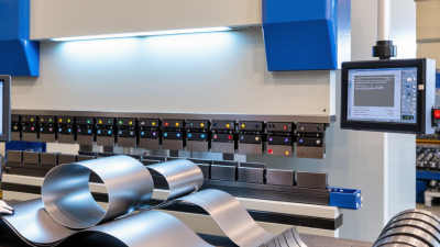
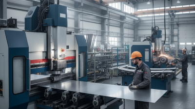
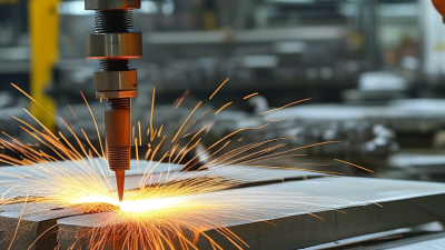
Metal bending is the controlled deformation of metal into an angle, curve, or formed profile. It appears in automotive frames, electrical enclosures, aircraft panels, and everyday brackets. The process may look simple. It is not.
A press brake applies force through a punch and die. The metal stretches on its outer surface and compresses inside the bend. Between them lies a neutral axis with little length change. Engineers use bend allowance to estimate the developed flat length. They also consider material thickness, tensile strength, grain direction, tooling radius, and springback. Professor Taylan Altan, a leading authority in metal forming, stated, “Successful forming requires understanding the material, the tooling, and the process.” That principle remains practical on the shop floor. A sharp die may create a tight bend, but it can also mark or crack the workpiece.
Metal bending depends on accurate measurement and disciplined process control. Operators check the first part with gauges or coordinate measuring equipment. They adjust the ram position when springback changes the final angle. A two-degree error can prevent a cabinet from closing. Small details matter.
The process is not perfectly predictable. Material batches can behave differently. Surface coatings may influence friction. Tool wear can slowly change results. This is where experience becomes valuable, although experience alone is not enough. Reliable bending combines verified calculations, machine setup records, inspection, and careful judgment. Understanding these principles makes metal bending safer, more repeatable, and easier to improve.
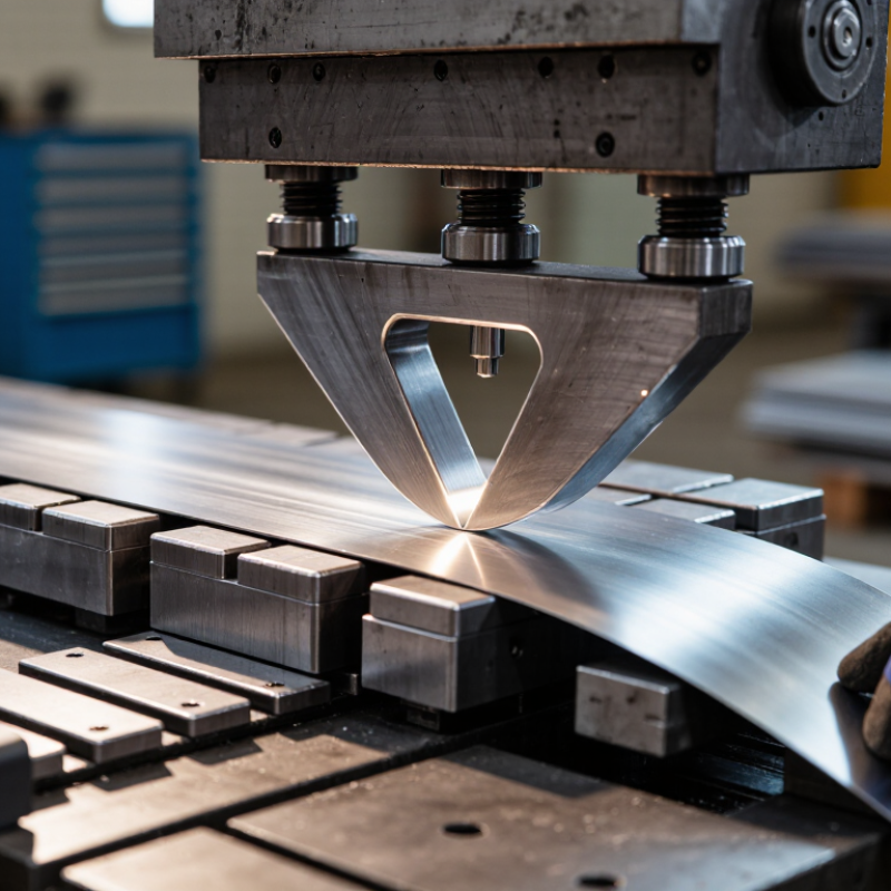
Metal bending is the controlled shaping of sheet, plate, tube, or bar around a planned axis. The process applies force until the material changes geometry without separating. In shop-floor practice, operators usually work with press brakes, rollers, or forming tools. The selected method depends on thickness, bend radius, material grade, and production volume.
The basic principle is controlled deformation. The outer surface stretches, while the inner surface compresses. Between them lies the neutral axis, where length changes very little. If force remains below the yield strength, the metal returns to its original shape. This is elastic deformation. Beyond that point, plastic deformation creates a permanent bend. It sounds simple. It is not always predictable.
Springback remains a practical concern. After unloading, the material partly recovers and opens the bend angle. Higher-strength steels usually require compensation because they store more elastic energy. Tool clearance and grain direction also influence cracking, distortion, and dimensional accuracy. A 2024 World Steel Association report recorded approximately 1.89 billion tonnes of crude steel production in 2023, showing the scale of materials requiring reliable forming control. Energy use matters too. The International Energy Agency estimates that iron and steel production creates about 7% to 9% of global energy-related carbon dioxide emissions. Better bend planning can reduce scrap, rework, and unnecessary forming passes. Still, calculations are only estimates. Real material behavior can challenge a perfect drawing.
Metal bending is the controlled deformation of sheet or bar material around a straight axis. A bending force creates a moment: the outer fibers are placed in tension, the inner fibers in compression, and the region between them is the neutral axis. When the applied stress exceeds the material’s yield strength, the metal retains its new shape after the force is removed.
How to read the chart: Young’s modulus measures stiffness, not bendability. Materials with a higher modulus require more force to produce the same elastic deflection. Actual bending force also depends on yield strength, thickness, bend angle, bend radius, tooling, and the width of the workpiece.
What Is Metal Bending and How Does It Work?
Metal bending reshapes a sheet, tube, or bar without removing material. The process relies on controlled force and accurate support. During forming, the outer surface stretches while the inner surface compresses. Between them sits the neutral axis, where length changes very little. This balance creates a bend around a planned radius. In real fabrication, calculations are only a starting point. Material hardness, grain direction, and thickness can change the result.
A press brake uses a punch and die to form straight bends. The punch pushes the metal into the die opening. Hydraulic systems apply steady force. Mechanical systems deliver faster, repeated movement. For long, gradual curves, roll bending uses several rollers. Each roller applies a smaller force across the workpiece. Tube bending may require a mandrel inside the tube. It helps prevent flattening and unwanted wrinkles.
Several forces act together during bending. Tensile force pulls the outside surface. Compressive force squeezes the inside surface. Shear force may appear near tight corners or poorly supported areas. Operators must also consider springback, which makes metal partly return to its original shape. A slightly deeper bend may compensate for it. Still, overcorrection can create another defect. I would check the first piece carefully, especially near the bend line. Small changes in tool position can affect the final angle. No setup is perfect. Surface marks, uneven pressure, and measurement errors still need attention.
Metal bending changes a straight sheet or bar into a controlled angle or curve. The work begins with material identification. Steel grade, thickness, grain direction, and yield strength affect every later decision. The World Steel Association reported 1,892.2 million tonnes of crude steel production in 2023. That scale makes repeatable bending essential, not optional.
The step-by-step process starts with reviewing the drawing and calculating the bend allowance. The operator then selects a press brake, punch, and die. Tool width matters. A narrow die can mark the surface or create excessive stress. The sheet is positioned against the back gauge, with its grain direction checked carefully. The machine applies force gradually. It may use air bending, bottoming, or coining, depending on the required accuracy.
The first bend is only a controlled test. The operator measures the angle with a gauge and checks for cracks, distortion, and springback. Springback happens when elastic energy returns after pressure is removed. It is easy to underestimate.
ASTM E290 provides methods for evaluating bend performance, while the International Energy Agency identifies iron and steel as responsible for about 7% of global energy-related emissions. Efficient setup reduces scrap and unnecessary rework. Still, the calculation is not perfect. A small variation in hardness can change the final angle. Experienced technicians adjust the bend depth, then inspect the next piece before continuing.
A practical overview of the main operations, controls, and quality checks used to form sheet and plate metal.
| Step | Process Stage | What Happens | Main Variables | Typical Data | Quality Check |
|---|---|---|---|---|---|
| 1 | Review the drawing | Identify the finished angle, bend radius, flange lengths, material, thickness, and permitted tolerances before setup. | Part geometry, bend sequence, datum locations, grain direction | Common bend angles include 90°, 45°, and 30°; dimensions are normally specified in millimetres. | Confirm that all dimensions and tolerances are defined. |
| 2 | Select the material | Choose sheet or plate stock with the specified alloy, temper, thickness, and surface condition. | Yield strength, tensile strength, thickness, ductility | Typical sheet thickness for press-brake work is about 0.5–6 mm; heavier plate requires higher forming force. | Measure thickness and verify the material specification. |
| 3 | Prepare the blank | Cut the flat blank to size using shearing, laser cutting, punching, or another suitable method. | Blank dimensions, cut quality, burr direction, holes and notches | Allow for bend allowance or bend deduction when calculating the flat pattern. | Check length, width, squareness, burrs, and feature locations. |
| 4 | Choose the tooling | Match the punch and die to the material thickness, required inside radius, bend length, and forming method. | Die opening, punch nose radius, tool length, tooling clearance | Air bending commonly uses a V-die; a frequently used starting ratio is V-opening ≈ 6–8 times material thickness. | Inspect tools for wear, damage, contamination, and correct alignment. |
| 5 | Set up the machine | Install the tooling, set the back gauge, establish the bend depth, and load the correct program or manual settings. | Press capacity, stroke, back-gauge position, tooling alignment | The required force increases with bend length, material strength, and thickness, and decreases as the die opening increases. | Perform a dry run and confirm safe clearances. |
| 6 | Position the workpiece | Place the blank against the back gauge and support it so the bend line is correctly located and stable. | Gauge position, edge alignment, part orientation, grain direction | A consistent datum reduces variation between parts and between successive bends. | Verify the first bend location against the drawing. |
| 7 | Apply forming force | The punch drives the material into or against the die, creating plastic deformation around the bend line. | Force, stroke depth, speed, bend method, contact pressure | Air bending contacts the material at the punch nose and two die shoulders; bottoming applies greater contact pressure. | Watch for slipping, cracking, excessive marks, and abnormal machine load. |
| 8 | Release and account for springback | After the punch rises, elastic recovery causes the angle to open slightly from the formed position. | Material strength, bend radius, thickness, forming method | Springback is often a few degrees, but the exact amount varies significantly by material and geometry. | Measure the released angle and compensate in the next cycle if necessary. |
| 9 | Complete the bend sequence | Repeat the operation in the planned order, using stable datums to prevent collisions and cumulative errors. | Bend order, part orientation, flange clearance, handling method | Short flanges and closed forms may require special punches, offset tools, or a revised sequence. | Check each completed bend before proceeding to the next one. |
| 10 | Inspect the finished part | Compare the formed component with the drawing and confirm dimensional, visual, and functional requirements. | Angle, flange length, inside radius, twist, surface condition | Typical inspection tools include a steel rule, caliper, angle gauge, radius gauge, and coordinate measuring equipment. | Record results, segregate nonconforming parts, and adjust the process when required. |
| Method | How It Forms Metal | Typical Use | Key Characteristic |
|---|---|---|---|
| Air bending | The punch partially drives the sheet into a V-die without forcing it fully to the die angle. | General sheet-metal fabrication and flexible angle production. | Lower force than bottoming, with angle controlled mainly by punch depth. |
| Bottoming | The material is pressed firmly against the die surfaces to establish the bend angle. | Applications requiring improved repeatability and reduced springback. | Higher force and closer tool-to-part conformity than air bending. |
| Coining | Very high pressure plastically compresses the bend region and creates a sharp, repeatable form. | Small bends, sharp details, and parts where springback must be minimized. | Highest forming force among the three press-brake methods. |
| Roll bending | Multiple rolls progressively curve the sheet or plate into a cylindrical or conical shape. | Large-radius curves, cylinders, cones, and long panels. | Suitable for continuous curves rather than isolated angular bends. |
Metal bending reshapes sheet, plate, tube, or bar without removing material. The workpiece is placed under controlled force. Its inner surface compresses, while the outer surface stretches. The final angle depends on material strength, thickness, grain direction, and bend radius.
Press brake bending is widely used for brackets, enclosures, frames, and machine panels. A punch pushes the metal into a die, creating a precise angle. Air bending offers flexibility, while bottoming provides stronger dimensional control.
Roll bending passes metal through rotating rollers. It produces large curves for tanks, ducts, architectural sections, and structural components.
Tube bending uses rotary tools or mandrels to form pipes. Internal support helps prevent wrinkles and flattening. Small details matter.
Stretch bending pulls the material while forming it around a die. This method suits aircraft sections, vehicle frames, and smooth architectural profiles.
Hot bending can shape thick or difficult metals after controlled heating. However, excessive heat may change hardness or cause distortion.
Experienced operators check springback before production. They also inspect bend marks, surface cracks, and angle variation.
A perfect result is not always achieved on the first attempt. Tool wear, uneven thickness, and poor support can affect accuracy. Testing a sample remains a practical safeguard.
Metal bending reshapes sheet or bar by applying force beyond its elastic limit. A press brake, roller, or forming tool controls that force. The material bends around a selected radius. Its outer surface stretches, while its inner surface compresses.
Accuracy depends on material grade, thickness, grain direction, and hardness. Two sheets with equal thickness can behave differently. Springback is a common problem. After pressure is released, the metal partly returns toward its original shape. Operators compensate by increasing the bend angle, but the correction is never perfectly predictable.
Tool condition matters too. A worn punch can leave uneven marks or change the bend line. Small alignment errors become visible across a long panel.
Temperature, lubrication, and clamping pressure also influence surface quality. Clean tooling helps prevent scratches and inconsistent movement. Measuring the first piece with a calibrated angle gauge and vernier caliper is practical. Experienced fabricators check several points, not just one corner. Still, inspection can miss distortion between measurements. Trial bends often reveal issues that drawings cannot show. That extra test consumes material. It can prevent a larger batch from failing. Digital controls improve repeatability, yet they cannot replace careful setup decisions. Record actual results, including unexpected springback. The next batch may expose a weak assumption.