How to Choose CAD CAM Software for Plasma Cutting
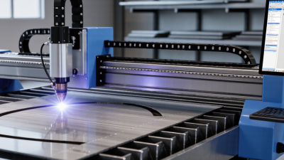
Choosing cad cam software for plasma cutting is a practical manufacturing decision, not a simple software purchase. The right system must convert drawings into clean toolpaths, control torch height, manage pierce delays, and reduce wasted plate. A crowded interface may look impressive. It can still slow production.
Manufacturing researcher Dr. David A. Dornfeld wrote, “Sustainability is not a single technology; it is a system-level challenge.” This principle fits plasma work closely. Software affects material usage, cutting time, energy consumption, and rework. A reliable system should support accurate nesting, lead-in control, kerf compensation, and automatic sequencing. It should also work smoothly with your plasma table, controller, and post-processor. Small mismatches can create large problems. A misplaced lead-in may leave a visible mark near a finished edge.
Look beyond feature lists. Test the software with real files, including thin sheet, thick plate, internal holes, and irregular remnants. Watch how quickly it generates paths. Check whether operators can edit those paths without calling a technician. Cloud tools may improve collaboration, but unstable internet access can interrupt production. That detail is easy to overlook.
Experience matters here. A shop cutting mild steel daily needs different tools from a school or prototype workshop. Compare licensing costs, updates, training, nesting quality, and technical support. Do not assume the most expensive package is best. It may be unnecessary. The honest answer can be uncomfortable: your current workflow might be the real bottleneck, not the software. A careful trial usually reveals that faster than a polished sales demonstration.
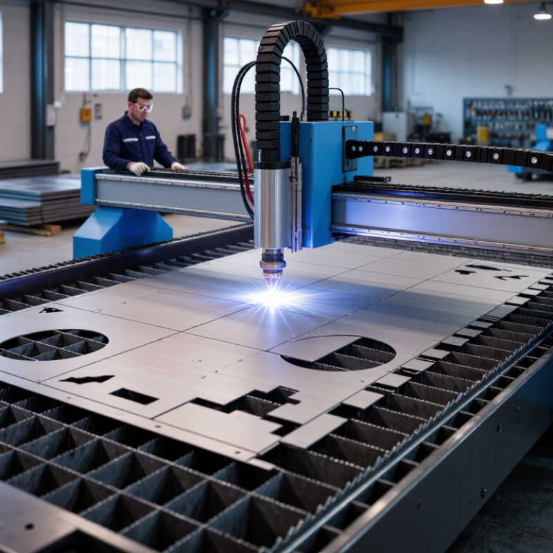
Define Plasma Cutting Requirements and Project Goals
Before choosing CAD CAM software for plasma cutting, define the job in measurable terms. Record material types, thickness ranges, sheet sizes, expected monthly output, and required edge quality. Also note whether the machine uses air, oxygen, or another approved gas. These details influence nesting, toolpath settings, pierce delays, and consumable planning.
ISO 9013 evaluates thermal-cut edges through geometry, perpendicularity, and surface characteristics. Your software should expose settings that support these checks, not hide them behind automatic presets. The International Federation of Robotics reported 541,302 industrial robot installations worldwide in 2023. This shows why automation matters, but automation alone does not fix unclear requirements. Decide whether your goal is faster nesting, fewer failed pierces, lower scrap, or repeatable production. Measure the current baseline. A perfect estimate is rarely possible.
Tips: Test the software with three real parts, including a small hole, a sharp corner, and a long contour. Compare cycle time, predicted scrap, and actual cut quality. Ask operators to review the workflow. Their practical experience often reveals problems that a specification sheet misses. Keep one trial result as evidence. It may challenge your original assumptions. According to the World Steel Association’s 2024 outlook, global steel demand remains near 1.75 billion tonnes, so material efficiency deserves close attention. Define acceptable kerf variation and minimum hole diameter before purchasing. Otherwise, “easy to use” may become an expensive and vague requirement.
Compare CAD CAM Design and Toolpath Features
How to Choose CAD CAM Software for Plasma Cutting
Choosing CAD CAM software for plasma cutting starts with the design workspace. Test how easily it creates precise profiles, holes, slots, and angled corners. A clean drawing should convert into usable geometry without hidden gaps. DXF import matters, but reliable cleanup tools matter more. In daily fabrication, tiny overlaps can create unwanted cuts or stalled toolpaths.
Compare toolpath controls with equal care. Look for adjustable lead-ins, lead-outs, kerf compensation, pierce delays, and cutting order. These settings affect edge quality and part accuracy. A strong nesting tool can reduce sheet waste while keeping small parts stable. Simulation should show pierce points and rapid movements clearly. Watch the corners closely. That is where problems often appear.
Experienced operators also check material libraries and post-processing options. Presets save time, but they are not always correct for every torch, thickness, or air setting. I prefer software that allows manual edits without hiding important parameters. It should also flag open contours, duplicate lines, and impossible pierces. No setup is perfect. I have seen a clean drawing produce poor cuts after one overlooked lead-in. Test a sample part, measure the finished edges, and record the changes. Reliable software supports this feedback instead of treating every job as automatic.
Evaluate Material, Thickness, and Machine Compatibility
Choosing CAD/CAM software for plasma cutting starts with the material you actually process. Mild steel, stainless steel, and aluminum transfer heat differently, so one cutting profile may not suit every job. Check whether the software lets you set material-specific parameters, such as cutting speed, torch height, and kerf width. Small changes matter. A narrow kerf can affect how tightly parts nest on a sheet, while incorrect settings may leave rough edges or excessive dross.
THICKNESS
Thickness deserves equal attention. A program that handles thin sheet well may struggle with plate, where slower cuts and different pierce settings are needed. Review the software’s supported thickness range against your regular work, not just an occasional project. Test a sample cut, then compare the actual edge with the settings on screen. I have seen a clean-looking simulation hide a poor result. The machine, consumables, and material condition all play a part.
Machine compatibility is practical, not just a checkbox. Confirm that the software can export a file format your controller reads, and that its postprocessor supports your table’s motion and torch controls. Check how it handles pierce points, lead-ins, and cut sequencing; these details affect starts, corners, and sheet stability. Ask for a trial file or run a small test pattern before committing. It may take longer. That is still better than discovering a mismatch halfway through a full sheet.
Assess Ease of Use, Automation, and Workflow Integration
A plasma-cutting shop can lose time before the torch even fires.
A useful CAD CAM system should make everyday tasks clear: importing a drawing, setting material thickness, choosing a cut path, and checking lead-ins. New operators should be able to spot errors without digging through layers of menus. Try a sample part, such as a bracket with several small holes, and watch how many steps it takes to prepare. Clear previews matter. A misplaced lead-in can leave a visible mark or weaken a narrow feature.
Automation should reduce repetitive work, not hide important decisions.
Look for automatic nesting, common-line cutting, and toolpath suggestions, then check whether settings can be reviewed and adjusted. For example, nesting may save sheet material, but tightly packed parts can make heat distortion harder to manage. The software should flag collisions and offer practical warnings. Not every suggestion will fit your machine or material. That is worth remembering.
Workflow integration is just as important.
Check whether the system can exchange common drawing files, preserve dimensions, and pass confirmed programs to the machine without manual re-entry. A test using a real shop drawing can reveal missing fonts, shifted geometry, or extra cleanup. Ask operators to try the workflow themselves. Their feedback may be blunt, and useful. A system that fits existing quoting, file storage, and job tracking can prevent small handoff errors from becoming wasted plate and machine time.
Review Support, Licensing Costs, and Software Reliability
When choosing CAD/CAM software for plasma cutting, judge support by what happens during a real production stoppage. Ask whether help is available during your shop’s working hours, and whether technicians can troubleshoot postprocessors, torch-height settings, and file-import errors. Request a sample response-time commitment in writing. A polished help page is useful, but it cannot replace a person who understands a cut file and a machine setup.
Licensing deserves the same scrutiny as the quoted price. Flexera’s 2024 State of ITAM Report identifies software-cost management as a continuing challenge for organizations, a reminder that purchase price rarely tells the whole story. Check renewal terms, seat limits, offline access, and fees for updates or extra machines. Then calculate the cost across several years. Small print matters. I would also test the software on an older shop computer; a feature-rich interface that lags while nesting parts can quietly waste operator time.
Reliability is not just whether the program opens. It includes stable toolpaths, dependable file exports, and recovery after a crash. Uptime Institute’s 2024 outage analysis reported that 54% of surveyed organizations’ most recent significant outages cost more than $100,000. That figure concerns digital infrastructure, not plasma software specifically, so treat it as context, not a direct forecast. Run a trial using your own drawings, controller, and material settings. Keep a backup workflow. I still wouldn’t trust a vendor demo alone.