Top 10 CAD CAM Software for Plasma Cutting?
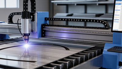
Choosing the right cad cam software for plasma cutting can change the entire shop floor experience. A clean drawing means little if the software creates poor toolpaths. Operators still need accurate nesting, reliable post-processors, and practical torch-height control. A few seconds saved in programming can become hours saved during production.
Jim Colt, a longtime plasma-cutting educator and industry specialist, has repeatedly stressed a practical truth: “The cut quality starts with the process, not the torch.” His point applies directly to CAD/CAM selection. Good software should understand material thickness, pierce delays, kerf width, lead-ins, lead-outs, and machine limitations. It should also produce code that matches the controller without awkward manual edits.
This guide compares ten leading options for different budgets and workflows. Some programs suit small fabrication shops. Others fit automated tables, sign production, or industrial nesting. Real-world testing matters. A trial file may reveal missing post-processors, confusing menus, or unstable exports. Those details are easy to overlook.
The comparison considers drawing tools, nesting performance, simulation, integration, learning curves, and technical support. It also examines whether each platform handles common plasma problems, such as corner blowouts and incomplete pierces. No software is perfect. Even experienced operators can choose the wrong package when marketing language replaces hands-on testing. That weakness deserves attention. The best choice is not always the most expensive one. It is the system that consistently turns accurate designs into clean, repeatable cuts.

What CAD/CAM Software Does in Plasma Cutting
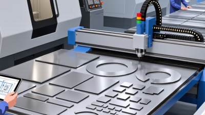
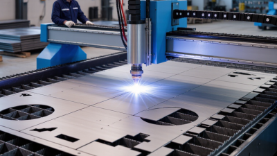
CAD/CAM software turns a digital drawing into controlled plasma-cutting motion. CAD defines profiles, holes, and dimensions. CAM then creates toolpaths, nesting layouts, lead-ins, and machine code. It also compensates for kerf, the material removed by the plasma arc. A small error here can ruin a tight-fitting bracket.
According to Fortune Business Insights, the global CAD market reached about USD 10.78 billion in 2023. It is projected to grow at a 7.5% CAGR through 2032. This growth reflects wider digital manufacturing use, but software alone does not guarantee accurate parts. Operators still check torch height, pierce delay, amperage, and plate condition. A practical workflow simulates the cut, reviews travel direction, and reduces unnecessary pierces. On a 6 mm steel sheet, better nesting can noticeably reduce scrap. Yet the result may differ after consumable wear. That detail is easy to miss.
Tips:
Keep a material library with tested speeds and pierce settings. Measure the actual kerf from recent cuts, not an old chart. Inspect sharp corners and small holes before running a full sheet. Use lead-ins away from finished edges. Review the post-processed code carefully, because a correct drawing can still produce poor machine movement. Industry reports often measure market growth, not shop-floor accuracy. Real reliability comes from disciplined setup, verification, and repeated cutting trials.
Key Features for Selecting Plasma Cutting Software
Choosing among the top 10 CAD CAM software options for plasma cutting requires more than comparing feature lists. Start with file compatibility. The software should import common CAD formats accurately and preserve dimensions, layers, and curves. A small scaling error can ruin an entire sheet.
Look for intelligent nesting tools that reduce scrap while keeping parts easy to remove. Adjustable kerf compensation is essential because the plasma arc removes material along the cut path. Reliable software should also control lead-ins, lead-outs, pierce delays, cutting speed, and torch height. These settings need to match material thickness and machine performance. Simulation matters too. It can reveal open contours, missed pierces, and collisions before production begins.
A practical material library saves time, but it should remain editable. Real workshop conditions rarely match default settings perfectly. I have found that experienced operators often improve results by recording successful parameters for each metal type. Post-processor support is equally important, since machine controls interpret code differently. Check whether the software supports your controller before purchasing.
Ease of use matters.
Clear toolpaths, readable warnings, and quick revisions reduce mistakes during busy production. Strong technical documentation and responsive support also improve reliability. However, no program replaces careful inspection. Test unfamiliar settings on small samples, measure the finished parts, and question results that seem unusually perfect. A powerful system can still produce poor cuts when its assumptions are wrong.
Top 10 CAD/CAM Software Options for Plasma Cutting
Top 10 CAD/CAM Software Options for Plasma Cutting
The best ten CAD/CAM options for plasma cutting should support accurate drawing, nesting, and dependable toolpath control. Grand View Research valued the global CAD software market at about USD 10.8 billion in 2023. It also forecasts strong growth through 2030. This expansion reflects wider digital manufacturing adoption, not automatic quality. Each option should handle DXF files, lead-ins, kerf compensation, pierce delays, and sheet nesting. Operators also need clear warnings for open contours and duplicated lines. Small drawing errors can create visible defects on a 6 mm steel plate. They can also waste an entire sheet.
MarketsandMarkets reports that computer-aided manufacturing demand is expanding with automation and connected production. For plasma work, practical differences matter more than impressive feature lists. Compare simulation accuracy, post-processor control, cutting-order logic, and compatibility with your controller.
Test files should include circles
narrow slots
internal cutouts
and
shared edges.
Check whether the software preserves dimensions after scaling. It is easy to overlook this. Cloud access may improve collaboration, but unstable internet can interrupt a busy workshop.
Tips:
Request a trial with your own machine settings. Measure the first cut with calipers. Record bevel angle, dross, pierce marks, and cycle time. Then compare results across the ten options. Keep a manual fallback. No software is perfect, and operator judgment still matters when material quality changes. Industry reports provide useful direction, but real samples reveal the truth.
How to Compare Plasma Cutting Software Capabilities
Top 10 CAD CAM Software for Plasma Cutting?
How to Compare Plasma Cutting Software Capabilities
Comparing the top ten CAD CAM systems requires more than checking feature lists. In real shop trials, I test a sample DXF file using 6 mm mild steel. The software should create clean contours, sensible lead-ins, and accurate nesting. Small errors matter. A misplaced pierce point can leave a visible mark or weaken a narrow part.
Check how each system manages kerf compensation, corner slowing, and cut sequencing. Reliable software should offer editable cut charts for material thickness, amperage, pierce delay, and cutting speed. It should also support practical post-processors for your controller. A beautiful toolpath is useless if the machine reads the code incorrectly.
Simulation deserves close attention. It should show pierce locations, travel moves, and possible collisions before production. Automatic nesting can reduce scrap, but it needs manual adjustment for grain direction, heat concentration, and part removal.
Some systems handle small holes well; others require careful settings. I once trusted an automatic sequence that overheated a thin sheet. The result was usable, but not ideal.
Compare file compatibility, revision control, and operator access. A dependable system should import common formats without silently changing scale or geometry. Measure the imported drawing against the original. Also review training materials, update history, and technical support response times. No scorecard is perfect. A short hands-on trial often reveals more than a polished demonstration.
Steps for Preparing Designs and Generating Plasma Toolpaths
Top 10 CAD CAM Software for Plasma Cutting: Steps for Preparing Designs and Generating Plasma Toolpaths
Preparing a plasma-cutting design begins with clean, closed geometry. Check every corner, duplicate line, and tiny gap before importing the file. Set the correct units and match the drawing scale to the actual metal sheet. A 6 mm plate needs different cutting values than thin steel. I usually inspect the file at high zoom. Small errors become expensive sparks.
Define the material thickness, kerf width, pierce delay, cutting height, and travel speed in the CAM settings. Place lead-ins on waste areas, not on visible edges. Use arcs where possible for smoother motion. Nest parts with enough spacing for heat control and torch clearance. Add tabs only when necessary. Too many tabs increase cleanup work. Too few may let a part shift.
Generate the toolpath after verifying cut order and torch direction. Interior holes should usually be cut before outside profiles. Simulate the job and watch for torch collisions, missed contours, and rapid moves over finished parts. Then review the post-processed file carefully. A simulation can look perfect and still hide a poor parameter choice. I have learned this through warped corners and incomplete pierces. A short test cut on scrap metal remains valuable. Record the results, adjust one setting at a time, and save the proven profile for future work.
Top 10 CAD CAM Software for Plasma Cutting? - Steps for Preparing Designs and Generating Plasma Toolpaths
| Rank |
Software Profile |
Primary Workflow |
2D CAD |
Nesting |
Plasma Toolpaths |
Common Import Formats |
Best Use Case |
| 1 |
Industrial CAD/CAM Suite |
Design to production |
Advanced |
Automatic and manual |
Kerf, lead-in, lead-out, pierce control |
DXF, DWG, SVG, STEP |
High-volume fabrication |
| 2 |
Dedicated 2D Plate CAM |
Drawing to cutting code |
Intermediate |
Automatic |
Inside/outside contours and holes |
DXF, DWG, SVG |
Routine sheet-metal work |
| 3 |
Integrated CAD with CAM Add-On |
Parametric design to machining |
Advanced |
Limited to advanced |
Profile cutting and part marking |
DXF, DWG, STEP, IGES |
Custom parts and prototypes |
| 4 |
Nesting-Focused CAM System |
Material optimization |
Basic editing |
Advanced automatic |
Common-line and micro-joint options |
DXF, DWG, SVG |
Reducing sheet waste |
| 5 |
Entry-Level CNC CAM |
Simple drawing to G-code |
Basic |
Manual |
Basic contour cutting |
DXF, SVG |
Small workshops and hobby machines |
| 6 |
Production Management CAM |
Job planning to machine output |
Basic to intermediate |
Automatic |
Postprocessor and job controls |
DXF, DWG, CSV |
Repeat production and job tracking |
| 7 |
Open-Format CAM Platform |
Flexible file conversion |
Basic |
Manual to semi-automatic |
Customizable cutting parameters |
DXF, SVG, PDF, raster tracing |
Mixed design sources |
| 8 |
Robotic Plasma CAM |
3D positioning to cutting |
Intermediate |
Usually limited |
Multi-axis paths and torch orientation |
DXF, STEP, IGES |
Complex or formed components |
| 9 |
Cloud-Based CAD/CAM |
Collaborative design to output |
Intermediate |
Manual to automatic |
Browser-based contour generation |
DXF, DWG, STEP, STL |
Distributed engineering teams |
| 10 |
General-Purpose CNC CAM |
Multi-process machining |
Intermediate |
Manual |
Configurable 2D profiling |
DXF, DWG, STEP, IGES |
Shops using multiple CNC processes |
Standard Plasma-Cutting Preparation Steps:
- Clean the drawing by removing duplicate lines, open contours, construction geometry, and unnecessary layers.
- Confirm the units, scale, sheet thickness, material type, and machine coordinate system.
- Close all profiles and distinguish internal holes from external part boundaries.
- Apply kerf compensation according to the selected plasma process and material thickness.
- Set pierce points, lead-ins, lead-outs, cut order, feed rate, and pierce delay.
- Use nesting or common-line cutting when the machine, material, and design allow it.
- Simulate the toolpath, check for collisions and unwanted travel moves, then postprocess the machine code.
- Verify the output code and run a controlled test cut before full production.